Autonomous Paddling Boat
Sangwon Lee, Junkwon Jeong
'Autonomous Paddling Boat'
Conventional propeller-driven electric boats pose en
vironmental risks, including underwater noise pollution,
ecosystem disruption, and water quality degradation. To
address these issues, this study designs and fabricates a
novel electric paddling boat that mimics the low-impact
motion of a kayak. The core propulsion system is imple
mented with a planetary gear set, connected to a DC motor,
to drive three paddles simultaneously. A 60x40cm prototype
hull was constructed using plywood and styrofoam, and
equipped with an Arduino Uno and three ultrasonic sensors
to enable autonomous obstacle avoidance. Field tests con
f
irmed the vessel successfully floats and the basic avoidance
algorithm functions as intended. However, a vulnerability
to external forces, such as water currents, was identified.To
compensate for these weaknesses, GPS and geomagnetic
sensors were added to determine the current location and
heading, and this data was mapped onto an HTML-based
map. Furthermore, an RC receiver was integrated to allow
the user to switch between manual control and autonomous
navigation at any time. This research demonstrates the fea
sibility of a low-disturbance, autonomous exploration plat
form using planetary gears, which can be improved with
enhanced propulsion and additional sensors.
1. Introduction
Driven by stricter environmental regulations for internal
combustion engines and a growing demand for clean en
ergy, the small boat market is rapidly electrifying. In par
ticular, similar to the trend in electric vehicles, electric
outboard motors are becoming mainstream. Electric out
boards offer significant advantages, including low noise,
low vibration, eco-friendly operation, and precise control
lability.
However, the fundamental propulsion mechanism re
mains identical to traditional motors: generating thrust via
a high-speed rotating propeller. This method presents per
sistent environmental challenges, including physical threats
to aquatic life and water quality degradation from sediment
disruption (propeller wash).
To address this problem, we drew inspiration from
kayaking, a related marine leisure activity. A kayak is pad
dle operates by pushing water rather than churning it.
This mechanism poses a negligible threat to aquatic life and
significantly reduces the risk of water pollution. Recog
nizing that users often choose small boats over kayaks for
speed and automation, we conceptualized a boat driven by
electric-powered paddles. In essence, we aim to solve both
the inefficiency of manual power (a drawback of kayaks)
and the environmental impact of propellers (a drawback of
small boats) by merging the two concepts.
Therefore, this study aims to develop a novel electric
paddling platform that combines the eco-friendliness of a
kayak with the automation of a motor. We seek to present
its potential as an autonomous surface platform for explo
ration, capable of overcoming the environmental limitations
of conventional propulsion systems.
2. Related work
2.1. Environmental Impact of Electric Motors
While electric outboard motors are an improvement over
gasoline engines, they still generate significant underwater
noise and negatively impact aquatic ecosystems. Gaggero
et al. measured the underwater noise levels of electric boats
in the Miramare Marine Protected Area in Italy, comparing
their impact on marine species against traditional gasoline
boats.
The results showed that while electric boats produce less
low-frequency noise, they emit persistent high-frequency
noise, which can adversely affect dolphins and other ma
rine mammals. This noise can cause chronic stress and be
havioral changes in marine life, such as altered feeding pat
terns or avoidance of spawning grounds, potentially leading
to ecosystem disruption. [2]
2.2. Current Applications of ASVs
The use of Autonomous Surface Vehicles (ASVs) in marine
research has grown significantly. An ASV is an unmanned
platform that navigates the ocean surface, collecting diverse
data via various sensors and allowing for remote control.
This method enables safer and more efficient hydrographic
surveys compared to traditional human divers.
According to the International Hydrographic Organiza
tion (IHO), ASVs are used in numerous fields, including
seabed mapping, port structure inspection, autonomous en
vironmental monitoring, and coastal bathymetry charting .
Equipped with sensors like GPS, IMU, and cameras, ASVs
can measure depth, topography, and obstacle locations, vi
sualizing them as 3D data. Beyond safety, ASVs offer
cost-effectiveness by surveying large areas without large
ships or personnel. Furthermore, the concept of Swarm
Robotics, using multiple ASVs simultaneously, is enabling
even larger-scale, concurrent data collection. [4]
2.3. Planetary Gears for High-Torque Propulsion
Our boat is paddling mechanism requires the delivery of
high torque at low speeds. A planetary gear system, where
multiple gears share the load to transmit torque, is a highly
efficient structure for this purpose. This system consists of
a central Sun Gear, orbiting Planet Gears, and an outer
Ring Gear that encases them.
This structure offers several advantages. First, because
the planet gears distribute the load, the system can effec
tively transmit high torque at low speeds. Second, a plane
tary gearbox can be much smaller and more compact than
other gear types for the same torque output, making it ideal
for small-scale applications like our boat. These advan
tages make the planetary gear structure a suitable solution
for low-speed, high-torque electric motor drives, enabling
effective propulsion from a small motor. [3]
2.4. GPS-basedSurfaceRobotNavigationResearch
For the autonomous navigation of an ASV, it is essential not
only to move but also to accurately identify its position and
managethedriving path. Schmidt and Hansen(2020)evalu
ated path stability in water environments using a GPS-based
navigation algorithm. In particular, they proved that contin
uous position correction using GPS significantly improves
autonomous driving performance in unstructured environ
ments with water currents, such as rivers. This provides
important implications for this study, as it allows for the de
tection and analysis of path deviations caused by external
forces (currents) via GPS data. [5]
2.5. GPS and Wireless Communication-based Re
mote Monitoring
GPS information can be used not only for internal robot
control but also for real-time monitoring of the robot is sta
tus from a remote location. Zereik et al. (2018) proposed
a technology that transmits GPS data to an external server
via wireless communication and visualizes it on a map, con
firming that this can increase the operational efficiency and
safety of autonomous surface robots. This study also se
cured the possibility of expansion into a location tracking
and exploration platform by transmitting and receiving GPS
data along with the ultrasonic sensor-based avoidance algo
rithm. [1]
3. Method
This study is broadly divided into two main parts: hardware
design and software design.
3.1. Hardware
This subsection describes the physical components and ma
terials selected for the boat.
3.1.1. Hull Design and Material Selection
The boat hull must be rigid and have an overall density
less than water to ensure buoyancy. The materials consid
ered were compressed styrofoam (XPS), plastic (HDPE),
and marine plywood. Their respective density, structural
strength, and ease of fabrication are compared in Table 1.

Based on the hull requirements, marine plywood was se lected as the most suitable material due to its high structural strength and ease of fabrication. Although XPS and plastic have lower densities than plywood (providing more inherent buoyancy), they are ineffective without sufficient structural integrity.
A primary concern with using marine plywood is that while the material itself floats, the added weight of compo nents could increase the boat is total weight and risk sinking. This potential issue is addressed by laminating it with lower density compressed styrofoam to enhance overall buoyancy and create a composite hull.
3.1.2. Motor Selection
Twoconditions were considered when selecting the motors. First, a high torque was required for the paddles to generate thrust by pushing against the water. Second, since the plane tary gear connects the motor and the paddles, an excessively high RPM motor would put a large load on the 3D-printed gears. However, if the RPM is too low, the boat is overall speed becomes too slow.
Considering these factors, the TND 90RPM DC12V JGY370wormgearedmotorwasdeemedsuitable. Twomo tors were used, one for the left and one for the right propul sion system.
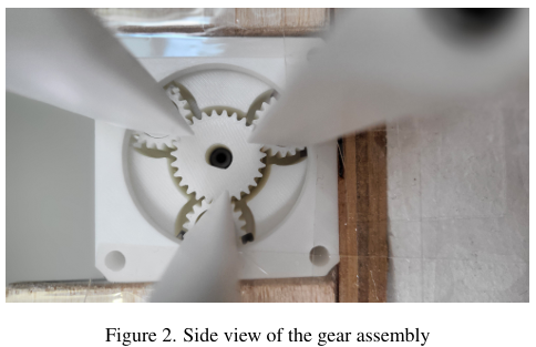
3.1.3. Propulsion Gear Design
For the planetary gear design, a base model was down loaded from Thingiverse and then modified to fit our spe cific needs using Tinkercad.
The 3D-printed assembly consists of a central sun gear, three surrounding planet gears, and an outer ring gear that engages all three planet gears. The motor shaft is inserted into the sun gear, causing the planet gears to orbit.
Ourkeydesignmodification wastoattach the paddles di rectly to the **ring gear**, not the planet gears. If attached to the planet gears, the paddles would both revolve (orbit) and rotate (spin on their own axis). By attaching them to the ring gear, the paddles only perform an orbital motion, elim inating self-rotation. We determined that adding rotational stress to the paddles, which already endure high loads from pushing water, would create too much uncertainty

3.1.4. Sensor Selection
The HC-SR04 ultrasonic sensor was chosen over infrared sensors due to its longer detection range and wider sensing angle
To detect obstacles across the boat is front, three sensors were installed. One sensor faces directly forward (Cen ter), and the other two are angled outwards at approximately 15 degrees (Left and Right), considering the sensor is plusminus 15 degree detection cone. A rear sensor was added after testing revealed its necessity.
3.1.5. Main Controller
An Arduino Uno WiFi Rev2 was used as the Master board (motor control, WiFi, GPS), and an Arduino Uno R3 was used as the Slave board (processing RC signals).
3.1.6. Paddle Design
To maximize water thrust, the paddle was designed with a parabolic profile when viewed from the side, and a rectan gular profile when viewed from the front. The dimensions of each paddle blade are 7cm in width and 13cm in height.
3.1.7. GPS Sensor
Ublox Neo 6m GPS module sensor is used.
3.1.8. Geomagnetic Sensor
HMC5883L geomagnetic sensor is used.
3.1.9. RC Receiver
A 6-channel RC flight simulation receiver was used to handle directional inputs and manual/autonomous mode switching.
3.2. Software
3.2.1. System Overview
The smart boat system proposed in this study is an Un manned Surface Vehicle (USV) platform that integrates GPS-based autonomous navigation and ultrasonic sensor based obstacle avoidance to move safely to a target point without human intervention. This system is designed as a scalable testbed for marine environment monitoring, data collection, or autonomous mission execution. The entire system adopts a dual control board structure to separate real-time control from communication/computation func tions, maximizing stability and responsiveness.
1. Master Control Unit (Arduino Uno WiFi Rev2): As the main brain, it handles autonomous driving algo rithms, motor control (L298N), sensor data processing (GPS, compass, ultrasonic), and Wi-Fi communication.
2. SlaveControlUnit(ArduinoUnoR3): Dedicatesitself to processing user RC commands and transmits control signals to the master board via I2C communication. This ensures immediate manual control transition in emergen cies.
3. Modes: Can switch between Manual and Autonomous modes. Manual mode allows user control via controller. In Autonomous mode, the motor control algorithm runs by default (obstacle avoidance), and if a destination is set on the map, it moves towards the destination while avoiding obstacles. This modular design prevents conflicts between complex sensor data processing and real time motor control and facilitates future expansion.

3.2.2. Motor Speed & Direction Control Algorithm
An algorithm was designed to control the direction and speed of the left and right motors based on the distance data from the three ultrasonic sensors. Differential steering (varying the speed and direction of the two motors) is used to turn the boat. The algorithm, which requires 3 consecu tive sensor readings to trigger a response (to prevent noise), is as follows:
1. Emergency Reverse: If either Sensor 1 or Sensor 2 de tects an obstacle at more then 10 cm for 3 consecutive times, both motors reverse at speed 100.
2. Turn Left (Pivot): If Sensor 1 detects an obstacle at 10 - 50cm(3consecutivetimes) while Sensor 2 detects at > 50 cm, Motor A moves forward (255) and Motor B reverses (150).
3. Turn Right (Pivot): If Sensor 2 detects an obstacle at 10 - 50cm(3consecutivetimes) while Sensor 1 detects at > 50cm, Motor Areverses (150) and Motor B moves forward (255).
4. Comparison Decision: If both Sensor 1 and Sensor 2 simultaneously detect obstacles at 10 - 50 cm, the dis tances are compared. If Sensor 1 is closer, Condition 2 is executed; if Sensor 2 is closer, Condition 3 is executed.
5. Forward Cruise: If both Sensor 1 and Sensor 2 detect distances > 50 cm, both motors move forward at speed 255.
6. Rear Obstacle (Reverse): If Sensor 3 detects an ob stacle at more then 10 cm (3 consecutive times), both motors reverse at speed 100.
7. Front Obstacle (Forward): If Sensor 4 detects an ob stacle at �� 10 cm (3 consecutive times), both motors move forward at speed 100.
A priority hierarchy implies that when multiple states overlap, the action with the higher priority is executed. For instance, if Sensor 1 detects an obstacle at 30 cm and Sensor 2 at > 50cm(triggering Condition 2), while the rear sensor simultaneously detects an obstacle within 10 cm (trigger ing Condition 7), the higher-priority Condition 7 is applied. Consequently, the boat will move straight forward to avoid the rear collision.
3.2.3. GPS-based Location Tracking & Data Transmis sion
To extend beyond simple avoidance, GPS tracking was added to monitor location and path in real-time. GPS co ordinates are sent to Arduino, processed, and transmitted to a remote server via Wi-Fi for visualization on an external dashboard.
3.2.4. Autonomous Navigation Algorithm
When a user sets a destination on the GCS App, the boat moves autonomously.
1. Step 1 (Path Planning): Master board calculates az imuth and distance between current GPS and target.
2. Step 2 (Heading Control): Electronic compass (HMC5883L) measures heading. System calculates er ror between target and current heading and uses differ ential steering to correct direction.
3.2.5. Real-time Mapping on HTML
GPS data is displayed on an HTML map using Javascript.
1. Step 1 (Data Collection): Arduino Master collects Lat, Lon, and Heading and formats them into a packet.
2. Step 2 (Transmission): Arduino acts as a web server (Port 8080). When the Web App requests /ar duino/serial/read, it sends the packet (repeats every sec ond).
3. Step 3 (Visualization): Leaflet.js creates a map (ESRI satellite tiles). Javascript parses data and moves/rotates the boat marker.
4. Step 4 (Input): User clicks map - Coordinates sent to Arduino as URL - Arduinoupdatestargetvariables and activates autonomous flag57.

4. Experiments
This section describes the final fabrication steps, buoyancy calculations, and the results of the field test.
4.1. Waterproofing
To seal the hull, partition walls were first constructed from wood and coated with waterproof paint. Subsequently, the entire boat was sealed with waterproof tape to ensure water tightness. 3D-printed covers were used to seal the planetary gear openings.
4.2. Maximum Payload Calculation
The boat is hull was constructed as a flat base by laminating 30mmcompressed styrofoam onto 12mm marine plywood, creating a total thickness of 42mm. The base dimensions are 0.4m in width and 0.6m in length.
The hull base itself weighed approximately 2.02 kg. The payload capacity was calculated for a target submersion depth of 30mm (0.03m).
Given the submerged volume Vsubmerged (0.4m * 0.6m * 0.03m) = 0.0072 m*3, and the density of water (��water) ? 1000 kg/m��, the total supported mass mmax is 7.2 kg.
This payload capacity of 5.18 kg was estimated to be suffi cient for all onboard components (motors, battery, sensors, etc.), and the boat was expected to float well.

4.3. Noise Reduction
To ensure stable control with the 12V battery, the master board, slave board, GPS sensor, geomagnetic sensor, ultra sonic sensors, and RC receiver were connected in series. At this time, the geomagnetic sensor, master board, and slave board were connected via SDA and SCL pins for I2C com munication.While this connection reduced the possibility of signal discrepancies between sensors and boards, noise generated from one component affected the entire system, causing frequent Wi-Fi disconnection phenomena.First, to resolve high-frequency noise generated by the master board during Wi-Fi connection, decoupling capacitors were uti lized. A 10uF ceramic capacitor was connected between the Vout and GND of the Arduino Uno WiFi. Similarly, 10uF ceramic capacitors were connected between each sensor to filter out noise generated by individual sensors as much as possible.Finally, to eliminate signal uncertainty, 100k�� pull-up resistors were connected between the SDA/SCL pins and the power line, respectively. When a digital in put pin is left unconnected (Open) or connected only to a switch, the pin enters a floating state when the switch is open. A floating state refers to a condition where the pin is not definitely connected to High (VCC) or Low (GND) but is floating in the air. In this state, the voltage level of the pin can fluctuate irregularly due to minute surrounding electromagnetic noise or static electricity. Since the MCU perceives this uncertain voltage as random HIGH or LOW signals, unwanted malfunctions may occur.By connecting a pull-up resistor, power is supplied to the input pin through the resistor when the switch is open (default state), main taining the pin is voltage securely at HIGH and eliminating the floating state and noise. When the switch is closed (op erating state), the input pin is connected to GND. Although current flows through the resistor, the voltage at the pin is pulled close to the ground, becoming LOW. This ensures that the state of the input pin is definitely defined as either HIGH or LOW, preventing malfunctions caused by noise.
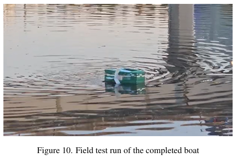
4.4. Field Test
4.4.1. First Field Test
The primary objective of the first test was to verify whether the motor algorithm operated correctly. Therefore, control was performed using only the Arduino Uno R3 board, and sensors were attached only to the front. The boat was placed in an actual pond, and it was confirmed that it floated well as expected. With the power connected while floating, the boat was made to move straight. As it approached the edge of the pond, it was confirmed that the motors rotated in op posite directions according to the algorithm to change the boat is movement direction. However, during the test, wa ter was being supplied to the pond, creating a water current. Whenthecurrent hit the side of the boat, the boat moved di agonally and eventually collided with the edge of the pond.
4.4.2. Conclusion of the First Field Test
Through the field test, we confirmed that the boat floated well as expected and that the motors operated correctly according to the detection distances of the sensors. Ad ditionally, using oars instead of propellers generated less noise and weaker wakes, confirming the intended eco friendliness. However, a regrettable point was that external forces such as water currents and wind were not considered. Wethought that sensing obstacles only in the front would be sufficient since the boat was set to move straight by default, but we realized that the boat could move in an unintended direction due to external forces. Therefore, there are two points to be improved. First, the size of the oars should be increased to maximize the influence of the oar is move ment over external forces. However, even with increased oar influence, there will be times when the external force is stronger, causing the boat to move opposite to the desired direction. The second improvement is to place sensors at the rear to prepare for such situations. This would allow the boat to avoid obstacles even when moving backward due to currents or wind. If the boat can automatically and contin uously avoid obstacles through these improvements, more efficient unmanned exploration will be possible.


4.4.3. Second Field Test
We improved the shortcomings identified in the first field test and conducted operations with a boat equipped with a system that identifies the current location via GPS and ge omagnetic sensors and maps it onto an HTML map. First, by increasing the size of the oars, we were able to move more stably and change direction reliably. Also, the sensors placed at the rear prevented collisions with obstacles behind the boat when it moved backward due to water currents.
The test was conducted in a river about 100 m wide, and a rope of approximately 50 m was connected in preparation for signal loss. In the early stage, manual operation was performed via the controller. After the middle stage, the mode was switched to autonomous navigation, and a desti nation was set on the HTML map for operation. The transi tion between manual operation and autonomous navigation worked well. It was confirmed that the obstacle avoidance logic executed continuously regardless of whether a desti nation was set during autonomous navigation, successfully avoiding obstacles. When a destination was set, the boat moved correctly toward the destination direction.


5. Conclusion
In this study, we designed and implemented a smart boat system integrating GPS-based autonomous navigation and obstacle avoidance functions using ultrasonic sensors. Through tests in an actual river environment, we verified the performance and feasibility of the proposed system and derived the following conclusions.
First, the dual control structure using Arduino Uno WiFi as the master controller and Arduino Uno as the manual op eration slave effectively distributed the complex sensor data processing and real-time motor control tasks, contributing to securing system stability. In particular, the immediate switching function between the manual mode using the RC controller and the GPS-based autonomous mode was con f irmed to be useful for emergency response and precision control.
Second, the autonomous navigation algorithm success fully generated a path to the target point and moved while maintaining direction using the HMC5883L compass. Ad ditionally, the obstacle avoidance logic using ultrasonic sen sors demonstrated basic autonomy by detecting and bypass ing obstacles on the driving path.
However, several limitations and areas for improvement were discovered during the actual operation test. To ensure safety, the test was conducted with the boat connected to a rope (50 m), which limited the operational radius. This, along with the limitations of Wi-Fi communication dis tance, became a constraint in verifying the boat is extensive autonomous driving performance. Future research needs to introduce long-range communication modules such as LoRa to expand the communication range and perform long-distance autonomous navigation tests in a completely wireless environment.
Furthermore, the current system has a limitation in that it relies on ultrasonic sensors and can only detect obstacles above the water surface. If object recognition technology based on cameras (Computer Vision) or LiDAR sensors are additionally introduced to detect underwater obstacles or f loating debris, safe autonomous navigation is expected to be possible even in more complex and unpredictable mar itime environments.
In conclusion, this study is significant in that it suc cessfully built a basic autonomous USV (Unmanned Sur face Vehicle) platform using low-cost sensors and micro controllers. This system can be utilized as basic research data for developing intelligent robots that perform various marine missions such as water quality measurement and marine debris collection in the future.
References [1] Julia AM Bachman and Benjamin N Tran. The bagel: De velopment of a stable towing frame and consistent procedures for sampling phytoplankton. In OCEANS 2018 MTS/IEEE Charleston, pages 1?6. IEEE, 2018. 2
[2] Tomaso Gaggero, Enrico Armelloni, Antonio Codarin, Carola Chicco, Maurizio Spoto, Carlo Franzosini, Saul Ciriaco, and Marta Picciulin. Electric boat underwater radiated noise and its potential impact on species of conservation interest. Ma rine Pollution Bulletin, 199:115937, 2024. 2
[3] Cheng-Chi Huang, Mi-Ching Tsai, David G Dorrell, and Bor Jeng Lin. Development of a magnetic planetary gearbox. IEEE transactions on magnetics, 44(3):403?412, 2008. 2
[4] Val Schmidt. Hydrographic survey with autonomous surface vehicles: A best practices guide. 2020. 2
[5] Woo-Ju Son, Jeong-Seok Lee, Hyeong-Tak Lee, and Ik-Soon Cho. An investigation of the ship safety distance for bridges across waterways based on traffic distribution. Journal of Ma rine Science and Engineering, 8(5):331, 2020.
