Development of a Robotic Arm Utilizing a Zero-Backlash Gearbox
Kim, Seojin Hwang, Hyeonseok
'Development of a Robotic Arm Utilizing a Zero-Backlash Gearbox'
This report describes the design and fabrication process of a robotic arm utilizing 3D printing technology and a zero-backlash gearbox architecture. The proposed system combines a Roller Pinion System (RPS) with a custom-adapted cycloidal drive to improve torque transmission efficiency while maintaining a compact and lightweight structure. To compensate for dimensional errors in FDM-printed PLA parts, structural reinforcement and tolerance adjustment were applied, and the RPS roller sleeve dimensions were optimized through a laser displacement experiment as OD 5.05 mm and ID 3.30 mm. Based on these results, the robotic arm was fabricated with a lightweight 5 mm plate linkage configuration and a 1-DOF active clamping gripper, demonstrating the feasibility of a low-cost, high-performance power transmission system through RPS-based backlash reduction and cycloidal torque amplification.
1. Introduction
1.1. Background and Motivation
In modern industrial robotics and high-precision automation, multi-axis robotic manipulators require compact, cost-effective, and low-backlash transmission systems to achieve high positioning accuracy. Traditional precision gearboxes, such as harmonic drives or metallic cycloidal drives, provide excellent anti-backlash performance, but they typically require high manufacturing cost and strict machining tolerances. These economic and mechanical barriers limit their accessibility for rapid prototyping, open-source robotics, and low-cost automated setups.
Additive manufacturing has recently emerged as a practical alternative for fabricating customized robotic components. However, 3D-printed involute gears often suffer from severe backlash, rapid tooth wear, and structural compliance due to the elastic deformation of plastics such as Polylactic Acid (PLA). These limitations are especially critical in robotic arms, where small joint errors accumulate across multiple links and directly reduce end-effector positioning accuracy.
To overcome these limitations, recent gearbox architectures such as the high-precision angular Roller Pinion System (RPS) replace conventional sliding gear contact with multi-point rolling contact. Inspired by this approach, this project focuses on designing and implementing an articulated robotic arm that combines 3D-printed RPS and cycloidal reduction mechanisms while optimizing the mechanical structure to compensate for the compliance and tolerance limitations of additive materials.
1.2. Proposed Robot Architecture
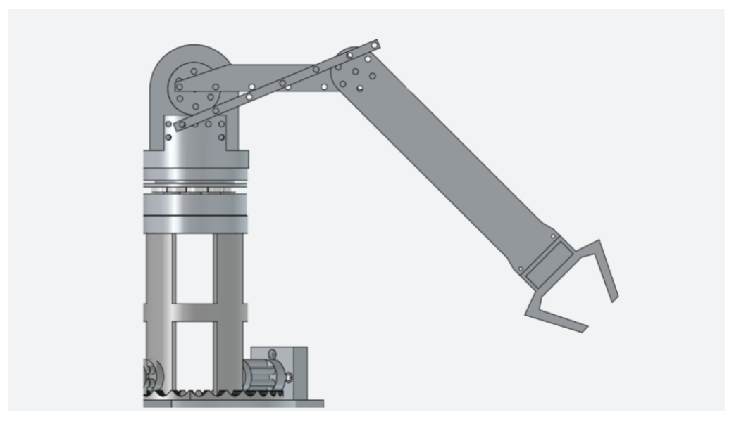
Figure 1. Overall robotic arm architecture and linkage configuration.
The proposed system is configured as an articulated robotic arm architecture featuring a 2-DOF positioning linkage integrated with a reconfigurable four-bar linkage mechanism. Structurally, the manipulator achieves global positioning through a one-axis base rotation (yaw) and a one-axis shoulder pitch elevation.
To minimize upper-arm inertia and improve dynamic load distribution, a non-parallel four-bar linkage mechanism using a lightweight plate configuration is deployed for the secondary arm segment. Unlike conventional rigid parallel linkages that maintain a fixed terminal angle, this architecture introduces a multi-position linear indexing system with five discrete adjustment holes on the chassis frame. By changing the grounding pivot pin among these five linear positions, the kinematic transmission relationship and proportional angular trajectory of the wrist joint can be reconfigured. The terminal stage of the manipulator features a 1-DOF active clamping gripper driven by an SG90 micro-servo motor for discrete grasping tasks.
1.3. Key Contributions
The primary engineering contributions of this project are summarized as follows:
- Compact shoulder gearbox and cycloidal drive verification: A compact shoulder gearbox was engineered and fabricated using fused deposition modeling (FDM) PLA. The prototype demonstrates that specialized high-reduction transmission mechanisms can be validated at a functional prototype level without relying on expensive CNC machining or metallic gear cutting.
- Mass-center optimization through reconfigurable linkage: A non-parallel four-bar mechanism with a multi-position linear indexing system was developed. By displacing heavy actuators and gearboxes with lightweight structural links, this configuration shifts the system's center of mass toward the primary base pillar, thereby minimizing the gravitational torque overhead.
- Empirical elasticity and tolerance compensation: Mechanical solutions were introduced to suppress structural compliance in additive materials, including an integrated radial retention wall, extended axial bushings, and RPS roller sleeves. These design revisions reduce joint runout and minimize macroscopic backlash through empirical sleeve and interface optimization.
2. Related Work
2.1. High-Precision Transmissions in Robotics
In robotics and precision automation, the selection of a speed reduction mechanism is critical because the joint transmission directly affects payload capacity, positioning repeatability, and dynamic response. High-precision robotic systems have commonly relied on strain wave gears (harmonic drives) and industrial-grade cycloidal drives.
Harmonic drives use a flexible internal gear to achieve near-zero backlash and high reduction ratios within a compact volume. However, they are susceptible to torsional compliance, can be fragile under sudden shock loads, and are often too expensive for low-cost experimental platforms. Industrial cycloidal drives provide a more robust alternative by transferring torque through eccentric cams and epitrochoidal disk profiles. Because the load is distributed across multiple internal pins, cycloidal mechanisms can achieve high shock resistance and high torque density.
Despite these mechanical advantages, standard metal-machined cycloidal drives require extreme geometric tolerances. When researchers attempt to replicate these geometries using standard Additive Manufacturing, the structural compliance and surface roughness of plastics like PLA introduce severe friction, erratic tracking, and localized binding.
2.2. The Roller Pinion System
To address the friction and precision limitations of conventional gear teeth, recent open-source robotics work has explored rolling-contact alternatives, especially the Roller Pinion System (RPS). The RPS replaces the sliding engagement of spur or involute gears with independent RPS rollers that move along a customized trochoidal tooth profile. The main advantage of this architecture is the reduction of sliding friction and heat generation, which is particularly useful when the main gear body is fabricated from thermoplastic material.
When at least two rollers remain engaged during directional reversal, the clearance-induced dead band can be mechanically suppressed, enabling near-zero-backlash transmission. Building upon these foundational concepts, this research introduces a hybrid multi-stage transmission architecture optimized for low-cost articulated manipulators, integrating a custom-adapted cycloidal drive with a compact shoulder gearbox.
3. Experiments
This section presents the experimental validation process used to optimize the compact shoulder gearbox for the robotic arm. Although the RPS mechanism is designed to reduce backlash through rolling contact, the fabricated gearbox still contains residual backlash due to FDM printing tolerance, surface roughness, elastic deformation, and assembly clearance. Therefore, a backlash measurement setup was constructed, and a sleeve-tuning experiment was conducted to identify sleeve dimensions that minimize backlash while maintaining stable rotation.
3.1. Experimental Setup for Backlash Measurement
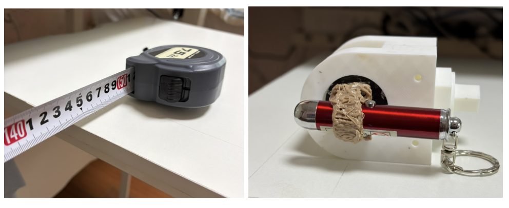
Figure 2. Experimental setup for backlash measurement.
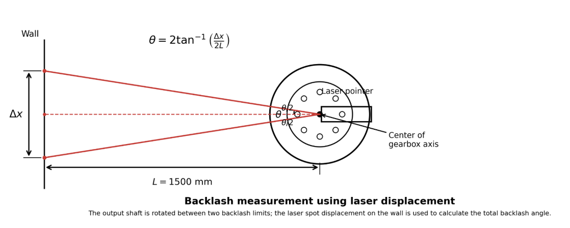
Figure 3. Laser displacement measurement principle.
The objective of the experimental setup was to measure backlash at the output shaft of the compact shoulder gearbox. In this experiment, backlash refers to the empty angular motion of the output shaft that occurs before power transmission begins after the rotation direction is reversed. Because this angular motion is small and difficult to measure directly, a laser displacement method was adopted.
The gearbox body was fixed to the table using clamps, and the input shaft was also clamped to prevent unwanted rotation. A laser pointer was attached to the output shaft using a temporary fixture, and the beam was projected onto a wall placed 1500 mm away. When the output shaft rotated by a small backlash angle, the laser spot moved by a larger distance on the wall. The backlash angle was calculated from the measured laser displacement as:
θ = 2 tan-1(Δx / 2L)
where L is the distance from the laser rotation reference point to the wall, Δx is the distance between the two laser spot positions, and θ is the total backlash angle of the output shaft.
Table 1. Equipment used for backlash measurement.
| Equipment | Function |
|---|---|
| Compact shoulder gearbox | Target gearbox for backlash measurement |
| RPS roller sleeve samples | Test variables with different OD and ID values |
| Laser pointer | Amplifies small output shaft rotation into wall displacement |
| Ruler | Measures the displacement of the laser spot on the wall |
| Measuring tape | Measures L and checks laser alignment |
| Clamps | Fix the gearbox body and input shaft |
| 3D pen fixture | Temporarily fixes the laser pointer to the output shaft |
3.2. Backlash Optimization via Custom Sleeve Tuning
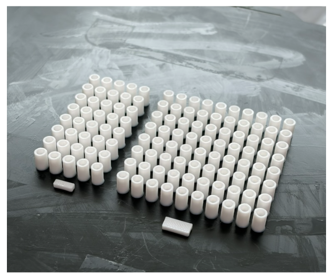
Figure 4. PLA sleeve samples fabricated for OD and ID tuning.
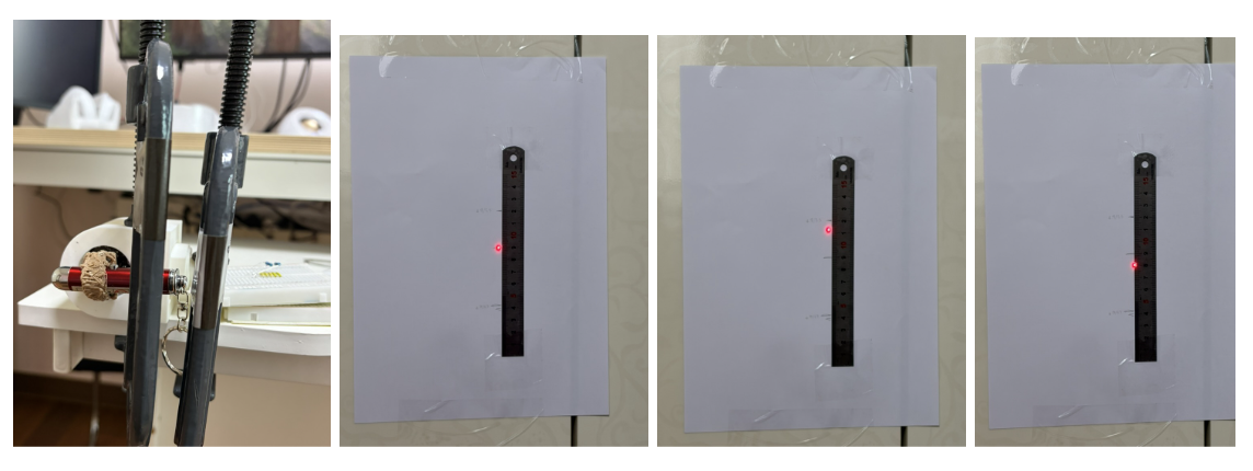
Figure 5. Backlash measurement process using two laser spot positions.
The sleeve-tuning experiment was performed in two stages. First, the inner diameter was fixed at ID 3.30 mm, and the outer diameter was varied to observe how OD affects backlash. For each sleeve condition, the output shaft was slowly rotated to one backlash limit, the laser spot position was marked, and the procedure was repeated five times. The average value was used as the representative backlash value.
Table 2. Backlash measurement results for OD tuning with ID fixed at 3.30 mm.
| OD [mm] | Avg. θ [°] | Std. [°] | Result |
|---|---|---|---|
| 4.90 | 0.2992 | 0.0118 | High backlash |
| 4.95 | 0.2355 | 0.0128 | Decreased |
| 5.00 | 0.1914 | 0.0142 | Decreased |
| 5.05 | 0.1306 | 0.0097 | Minimum |
| 5.10 | 0.1857 | 0.0152 | Increased |
Table 3. Backlash measurement results for ID tuning with OD fixed at 5.05 mm.
| ID [mm] | Avg. θ [°] | Std. [°] | Result |
|---|---|---|---|
| 3.25 | 0.1629 | 0.0177 | Slightly lower backlash; tighter fit |
| 3.30 | . | . | Best assembly and rotation stability |
| 3.35 | 0.1687 | 0.0125 | Slightly higher backlash |
The OD tuning result showed that backlash generally decreased as the sleeve OD increased from 4.90 mm to 5.05 mm. A larger OD allows the roller to contact the crown gear earlier, reducing the empty motion of the output shaft. However, when the OD increased further to 5.10 mm, the backlash increased again, indicating that an excessively large sleeve can cause interference, contact resistance, or unstable rolling along the gear profile.
Based on the OD and ID tuning experiments, OD 5.05 mm and ID 3.30 mm were selected as the appropriate sleeve condition for reducing backlash while maintaining stable rotation.
4. Method
4.1. Proposed Mechanical Design
4.1.1. RPS-Based Gearbox Design Methodology
The fundamental transmission architecture of the proposed robot is centered around the Roller Pinion System (RPS). To ensure high geometric fidelity and kinematic accuracy, all transmission components were engineered within a hybrid parametric CAD workflow, using both Autodesk Fusion 360 and FreeCAD. Unlike conventional involute gearing, the RPS profile was generated through a kinematic subtraction methodology, where the trochoidal tooth flanks were derived by simulating the continuous rolling path of the RPS rollers. The system utilizes two distinct types of customized gearboxes: a primary turntable gearbox and a compact shoulder gearbox.
4.1.2. Primary Turntable Gearbox
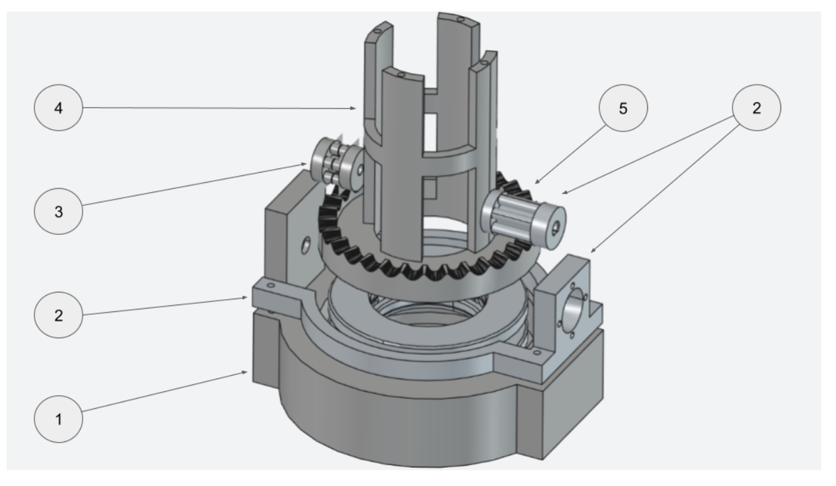
Figure 6. Exploded view of the primary turntable gearbox.
The first axis of the manipulator utilizes a large-scale turntable gearbox designed to serve as the primary structural foundation. The overall turntable gearbox consists of the following components:
1. Turntable gearbox housing and thrust bearing: A cylindrical housing incorporating a 51310 thrust bearing to distribute axial loads.
2. Radial retention wall as a motor mount and RPS roller: A structural wall that fixes the center axis of the crown gear and also serves as the mount for the turntable roller motor. The RPS roller is directly connected to the motor output shaft and transmits power to the crown gear.
3. Dummy roller: A counterpart roller installed to prevent torsion generated by the motor-driven roller.
4. Scalable column: A column interface that supports the upper manipulator structure and transmits the base rotation.
5. Crown gear: The primary crown gear forming the RPS mechanism together with the RPS roller.
- Load distribution and stability: A dedicated thrust bearing was integrated into the housing to isolate axial forces from the motor shaft, preventing structural misalignment during rotation.
- Oscillation suppression: A radial retention wall was integrated into the housing to fully enclose the crown gear. A dummy roller was positioned diametrically opposite to the primary RPS roller to provide a secondary contact point, ensuring axial balance and neutralizing lateral play.
- Actuation specifications: The gearbox features a reduction ratio of 5:1 and a diameter of 100 mm. The input stage is driven by an IG-32GM 07TYPE DC geared motor, capable of delivering up to 2.24 kgfcm of rated torque.
4.1.3. Compact Shoulder Gearbox and Actuator Integration
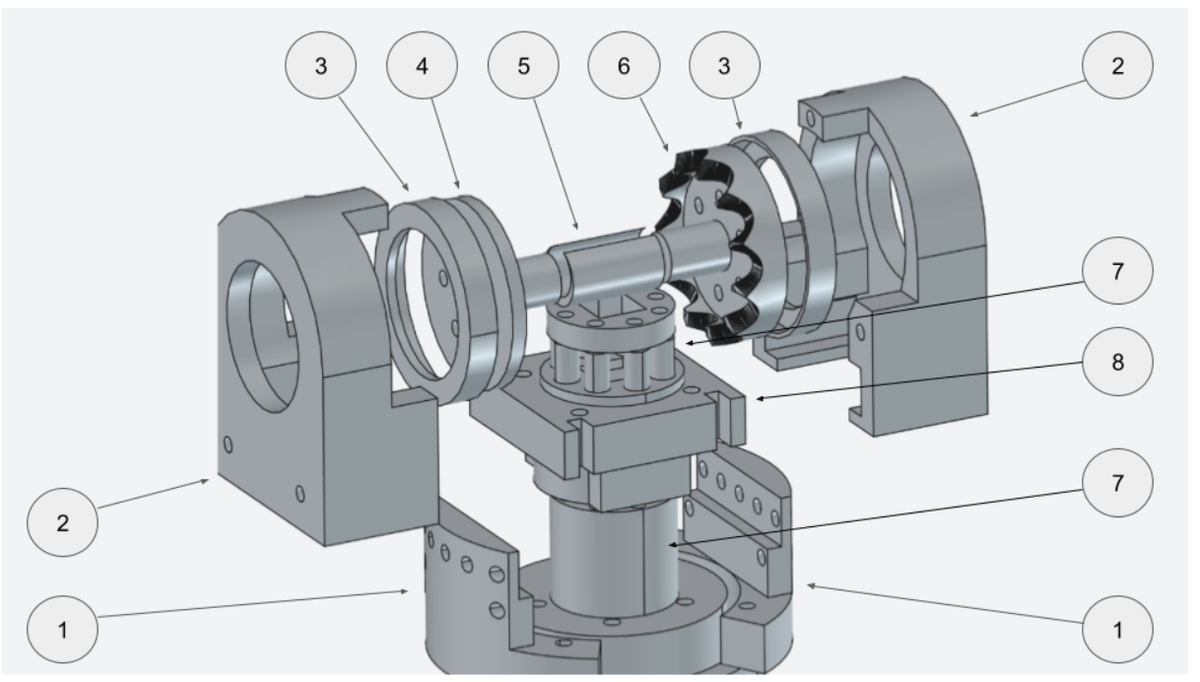
Figure 7. Exploded view of the compact shoulder gearbox.
The shoulder joint requires higher torque density within a constrained volume because it must overcome the moment arm of the upper-link assembly. The compact shoulder gearbox consists of the following components:
1. Shoulder gearbox mount: A mount that fixes the compact shoulder gearbox to the column, including five discrete adjustment holes to enable variable linkage adjustment.
2. Shoulder gearbox housing: The main structural housing of the compact gearbox.
3. Housing-to-gear spacer bushing: A bushing that maintains clearance between the gear and the housing to prevent friction.
4. Axial thrust balancer: A disc used to prevent shaft torsion and the lifting phenomenon of the crown gear.
5. Angular interface bushing: A bushing that reduces friction at the vertical intersection of the roller and crown gear axes.
6. Crown gear: A trochoidal tooth-profile gear used to derive high-precision and zero-backlash motion in the RPS.
7. RPS roller: A roller with a rotating sleeve that transmits torque to the crown gear.
8. Square bushing: A bushing used to secure the roller to the central shaft.
- Hybrid reduction scheme: The shoulder assembly adopts a modular reduction profile with an 11:8 RPS ratio. Torque is initially multiplied by a 1:10 custom-adapted cycloidal drive, which then interfaces directly with the 11:8 shoulder gearbox stage to achieve maximum mechanical advantage.
- Maintenance and durability: The final sleeve dimensions were determined through the backlash measurement experiment, where OD 5.05 mm and ID 3.30 mm were selected as the optimized condition.
4.1.4. 3D-Printed Cycloidal Drive Adaptation
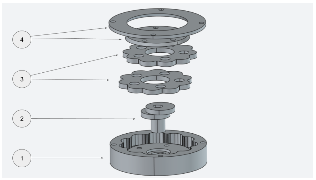
Figure 8. Exploded view of the adapted 3D-printed cycloidal drive.
The 3D-printed cycloidal drive consists of the following major components:
1. Cycloidal housing: A housing that integrates outer wall pillars with the internal cycloidal gear profile. It serves as the structural frame and the fixed reference for reduction rotation.
2. Elliptic eccentric cam: A cam connected to the motor input shaft with an elliptic offset. It converts high-speed rotation into eccentric orbital motion to drive the plates.
3. Stacked dual cycloidal plates: Two cycloidal discs stacked with a 180-degree phase shift. They counteract eccentric vibration and double the torque transmission capacity.
4. Interlocking output disc assembly: A tapered inner disc and a donut-shaped outer shroud ring that lock together, transmitting the reduced rotational output while providing axial restraint to eliminate structural play.
To achieve the high reduction ratio of 1:10 required for the primary stage of the shoulder axis, a thermoplastic cycloidal drive was integrated. Integrating this custom cycloidal stage within the spatial constraints of the structural pillar (inner diameter of 50 mm, outer diameter of 60 mm) enforced strict geometric limits. The reduction ratio was aggressively optimized to its physical upper bound of 1:10, and the center eccentric shaft bore was carefully sized at 9 mm to directly couple with the motor shaft while maintaining sufficient structural wall thickness and rigidity.
To ensure smooth operation and overcome localized binding caused by FDM layer lines, manual post-processing and sanding were selectively applied to the eccentric shaft. A thin, dedicated structural guide plate was integrated at the lower section of the shaft to prevent potential axis deflection and subsequent axial misalignment.
4.1.5. Multi-Axis Actuation via Mechanical Linkage
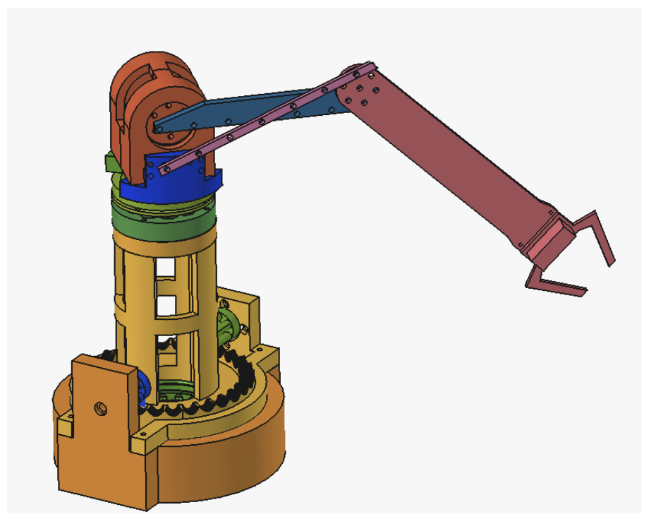
Figure 9. Multi-axis actuation layout using a reconfigurable linkage mechanism.
A critical vulnerability of 3D-printed articulated manipulators is the severe structural compliance and mechanical binding that occurs when heavy actuators are stacked sequentially along the arm. Placing a secondary high-torque gearbox directly at the elbow joint creates an excessive moment arm, causing the PLA structural frames to bend, shifting the gear axes out of alignment and locking the transmission.
To bypass this failure mode, the proposed manipulator avoids multi-stage modular stacking and instead utilizes a remote multi-axis actuation scheme driven by a lightweight 5 mm plate linkage configuration. By anchoring the heavy shoulder drive assembly close to the main base pillar, the overall upper-arm mass was drastically reduced.
The core of this mechanical linkage relies on a non-parallel four-bar mechanism connected via adjustable grounding pivot pins. By altering the position of the grounding pivot pin among five linear positions, the kinematic transmission matrix and the proportional angular trajectory of the wrist joint can be selectively reconfigured.
4.1.6. End-Effector and Control Interface
The terminal stage of the manipulator features a 1-DOF active clamping gripper driven by an SG90 micro-servo motor. To validate the fundamental kinematic capabilities and verify the multi-axis coordination of the physical assembly, a streamlined control interface was constructed. The primary software routine manages the basic operational trajectories of the arm, utilizing discrete position mapping to orchestrate pick-and-place tasks.
5. Conclusion
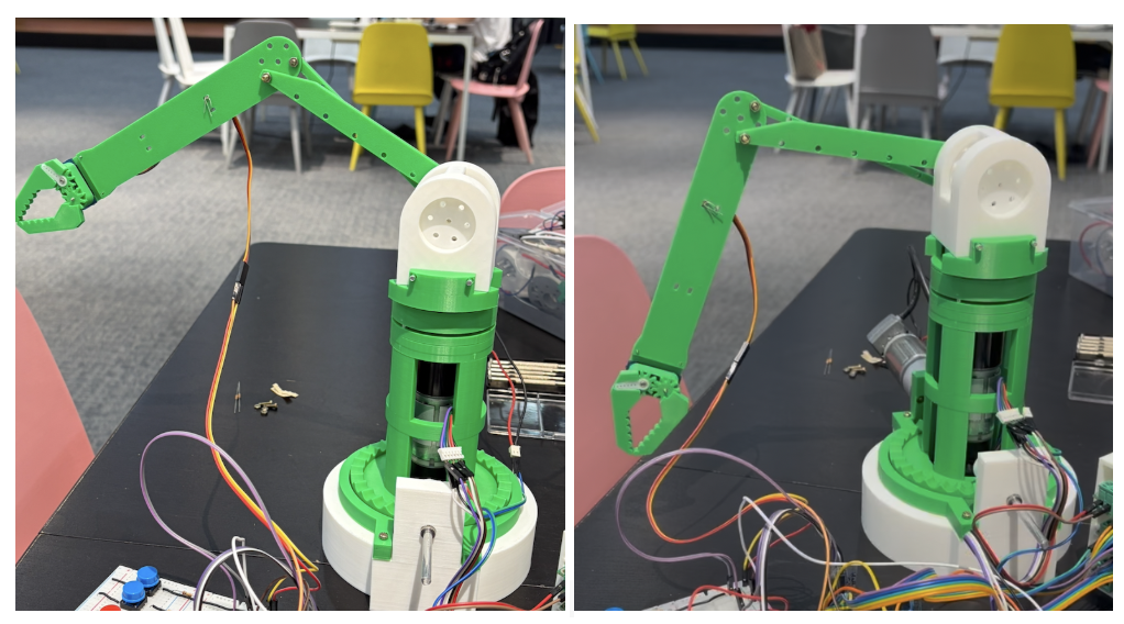
Figure 10 & 11. Final CAD model and fabricated robotic arm prototype.
This project successfully designed, fabricated, and validated a 3D-printed robotic arm using a zero-backlash gearbox architecture. By combining an RPS-based gearbox with a custom-adapted cycloidal drive, the system achieved compact torque transmission while addressing the torque limitations of small DC geared motors. Structural issues caused by FDM-printed PLA, such as backlash, elastic deformation, and assembly clearance, were reduced through reinforced gearbox geometry and empirical sleeve tuning.
The backlash experiment confirmed that OD 5.05 mm and ID 3.30 mm provide the most appropriate sleeve condition for stable rotation among the tested samples. Under this condition, the compact shoulder gearbox achieved the lowest measured backlash in the OD tuning experiment while preserving assembly and rotational stability. Based on this result, the optimized gearbox was integrated into the robotic arm with a lightweight 5 mm plate linkage configuration and a 1-DOF active clamping gripper.
Overall, the prototype demonstrates that low-cost additive manufacturing can be used to implement a functional robotic arm gearbox system when mechanical design and tolerance compensation are carefully combined. Future work should further quantify load capacity, long-term wear, and closed-loop positioning accuracy under repeated manipulation tasks.
References
[1] Mishin Machine. High precision angular gearbox, 3D printed and tested. YouTube, 2025.
[2] Liming Ma, Shuai Wang, and Jian Chen. Research on meshing characteristics of trochoidal roller pinion rack transmission. Applied Sciences, 12(11):5620, 2022.
[3] Y. Katayama, Y. Fukuoka, and I. Yoshida. Pinion and power transmission device. Taiwan Patent TW202100895A, January 2021.
[4] Aaed Musa. Parametric cycloidal gear drive. Hackaday.io, 2021.
[5] HowToMechatronics. What is cycloidal drive? Designing, 3D printing and testing. YouTube, 2022.
[6] Scarecrow23. Servo motor claw. MakerWorld, 2025.