Kinetic Art
Giryang Kang, Jihwan Kim
'Creating new dimensions of art by interacting engineer elements with traditional static art'
Kinetic art refers to artworks that generate a cooperative movement. Beyond its aesthetic aspects, kinetic art represents a diverse amalgamation of various technologies. In kinetic works, the control of movement involves managing disruptive elements such as oscillations caused by air flow or changes in the center of gravity. To minimize these disturbances, a meticulous design for kinetic art becomes essential. The search began with a study on the design and fabrication of mechanical motion mechanisms applicable to 'Kinetic Art,' aiming to express sculptural forms with dynamic motion through the fusion of dynamic mechanical devices.
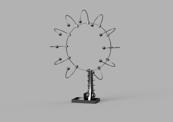
fig1. The 3D conceptual modeling
Kinetic art derives its name from the Greek word "kinesis," meaning "movement" or "motion." It represents an art form that emphasizes movement and dynamic elements within artworks. Kinetic art can manifest in various forms, including sculpture, installation art, painting, photography, lighting, and more. This art form highlights the interaction between the viewer and the artwork, creating a richer and more unique experience through movement or change. Kinetic art pieces distinguish themselves from traditional static art by incorporating elements such as environment, sound, light, etc., to interact and create new dimensions. These artworks often utilize electricity, mechanical devices, sensors, programming, and other technologies to generate movement. Examples of kinetic art include rotating sculpture, moving light installations, and interactive digital installations. The foundational structure is engineered to support an upper ring structure. The operational principle of the Kinetic Art involves the activation of five gears within the support structure. Upon activation, these gears initiate rotation, propelling the top gear, which is interconnected with the initial pivot joint. The rotational movement of the first pivot joint subsequently influences the following pivot joint, creating a sequential connection throughout connector. The entire pivot joint structure functions in this coordinated manner. This draft design of the Kinetic Art architecture has undergone modifications in its specifications through a series of trials.
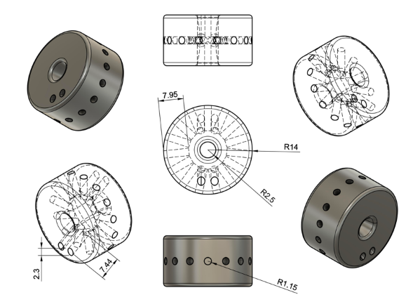
Fig2. Drawing of pivot joint
By obtaining the moment of inertia of the pivot joint based on the provided conditions, and extracting angular acceleration from the motor's speed, we determined the force at the point where the next pivot joint's connector touches?specifically, at a distance r from the rotation axis. Following the principle of action and reaction, this force is transmitted to the next pivot joint's connector, causing the rotation of the subsequent joint.
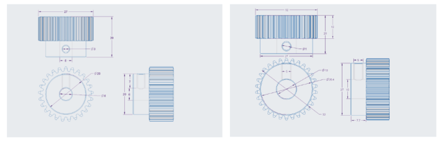
Fig3. Drawing of steel gears
The gear in charge of driving the main body is configured to receive force simultaneously on both sides, and this is to solve the problem that the driving time difference and power transmission difference from the first part to the last part of the ring are large when power is transmitted to one side. The 8 main gears connected to the main body were fixed and connected to a shaft on both sides, four each, so that they could rotate simultaneously with the force of the motor. In addition, a bearing was connected between the shaft and the main body so that smooth rotation could occur between the shaft and the main body. A bearing-embedded gears are connected to the ring and rotated the part constituting the ring. The module of all gears was unified to 1, so that each gear could fit and rotate smoothly.
