Visual Navigation
Finding direction in current location has been very important issue in navigation. Generally, we have used the Global Positioning System(GPS) which uses satellite communication. It is easy to knowing current location using GPS. But it has some limitation in indoor conditions or the weather condition which can hinder communication with satellite. There, recently, have been some tries including some sensors. For example, there are the range sensor, IMU(inertia measurement unit), encoder, vision and etc. These researches(Sukkarieh et al.,1999; Obradovic et al., 2007) has focus on the localization using its self-measurements without absolute coordinate system. Simultaneous Localization and Mapping is also similar well-known researches using them. But these methods are very complex with both large computation and various sensors. But we have already known the robustness of vision in navigation. For example, the Saharan ant(Cataglyphis Fortis) can find home direction without pheromone. Because the temperature of desert evaporates the pheromone from the ant. In this part, they use vision and odometry.

Path Integration of Saharan ant(Cataglyphis Fortis). (Left : reprinted from Wehner et al., 1996a, Right : Wehner andWehner, 1990)
Similar with Saharan ants, there have been a lot of cases of visual navigation. Dessert ant (Collett and Collett, 2000), honeybees(Kirchner and Braun, 1994), jellyfish(Garm et al., 2011) ,rodents(Etienne and Jeffery, 2004), fiddler crabs(Zeil and Hemmi, 2006), gerbils(Etienne et al., 1996; Mittelstaedt and Mittelstaedt, 1980) are the typical ones and these animals can do homing navigation using various senses like vision, olfactory, auditory, odometry, magnetic and etc (Collett and Collett, 2000;Mather, 1991; Luschi et al., 1996; Ugolini et al., 2010; Steck et al., 2010; Lent et al., 2010). Different to the recent researches like SLAM, these creatures has simpleness based on the small capacity brain. We have focus on this simpleness to make a new robust navigation method.
1. Snapshot Algorithm
As the Snapshot model is the method introduced in 1983 by cartwright and collet, it originally mimics the model of bee navigation. Also the snapshot method as the progenitor of the visual navigation have developed a number of the similar robot visual homing algorithms which use common assumption of this method. The key point of Snapshot model is that the agent remembers only first scene and last scene to find the homing navigation. First snapshot includes the surround information in azimuth direction (Nelson and Aloimonos, 1988). There are some researches (Zeil, 2012; Kohler and Wehner, 2005; Narendra, 2007; Collett, 2010; Reid et al., 2011) that insist the real creatures use the panormic information to navigation. The lower figure shows the principle of the snapshot model. The outer circle shows the panorama image of retina image and the inner circle shows the saved snapshot image. Then, the agent can find the homing direction which makes the current retina image same with home one.

Principle of Snapshot model. Ref: http://www.pigeon.psy.tufts.edu/asc/Biegler
The snapshot model is very robust and verified by both mathematically and mechanically.
2. Average Landmark Vector (ALV) model
Based on Snapshot model, the first algorithm is Average Landmark Vector method (ALV: Lambrinos et al., 2000). Two images are basically aligned with compass. The landmark vector set has landmark vectors which have the azimuthal location of each landmark with unit length. Then the mean of this unit vectors is Average landmark vector of the home site and remember it. In the next step, do the same operation with current image and get the ALV of the current position. Finally find the homing direction by subtraction between two ALVs.

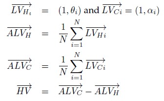
The left figure show the principles of each parameter methods(reprinted from [Yu and Kim 2012]) and the right formula shows the ALV model.
3. warping
Warping method finds the optimal pixel movement among the possible pixel matching. The pixels in the image have each distance and angle from each location. Then it tries to calculate the all pixel matching about distance and angle variances. Then, it extracts the optimal pixel matching with optimal homing direction. This method is very accurate but also slow by large computation.

Derivation of the warping equations (left: top view, right: side view). A robot moves from a snapshot location S to a current location C. The difference of azimuthal plane to 1-D warping. B. show the elevation changes for 2 location. It will be used in vertical scale modification for 2-D warping (reprinted from Moller et al., 2010; Moller, 2009)).
4. Descent in Image Distance (DID) method : Zeil et al., 2003
The main idea of DID is small movements to surrounds. The agent tries to find the direction which has smallest image difference among them. The image from each additional movement is compared with home snapshot. Later, it makes advanced version using matched filter to predict the moved image without additional movement.

Principle of the DID model using Matched filter. Two estimated images are made by applying two translational flow templates for perpendicular movement directions to the current image, (reprinted from (Moller et al., 2007)
5. Distance Estimated Landmark Vector(DELV) model : (Yu and Kim, 2010a; Yu and Kim, 2010b)
DELV is a new model based on distance estimation which can break the equi-distance assumption. It makes the additional movement along the heading direction to observe the azimuthal changes using these two images at one position. Then we can calculate the estimated distances to each landmarks using trigonometrical function. It can make the landmark vectors which have angular positions with estimated distances. The figure shows the principle of DELV.

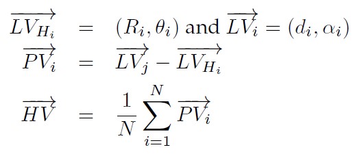
The left figure show the principles of DELV(reprinted from [Yu and Kim 2012]) and the right formula shows the DELV model.
Then we can find the homing direction using landmark arrangement method. It finds the optimal matching case with variance of both matching order and angle. Then our model can find the homing direction without reference compass.
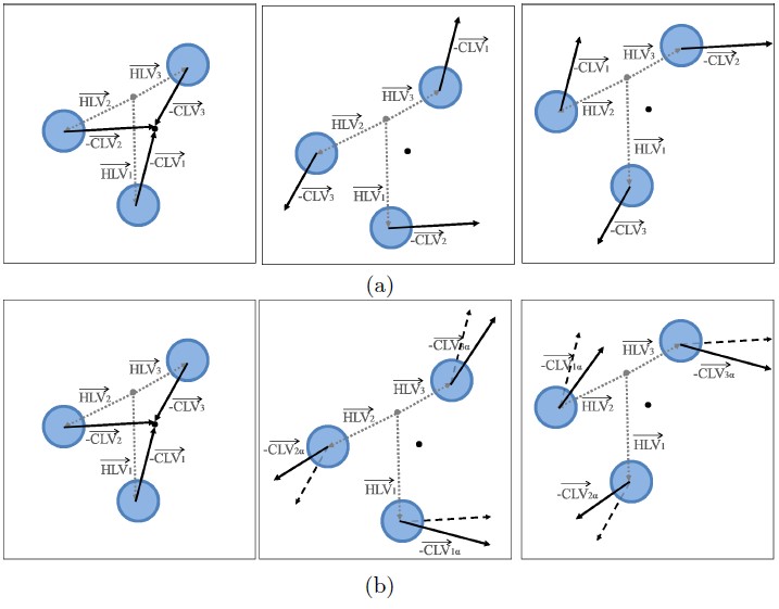
Principle of landmark arrangement method. The arrows mean the distance estimated landmark vectors and they are gathered like fist case with proper matching. Second and third one show the wrong cases with large variances.
Next, we apply our method using range sensor. Kinect and Laser(Hokuyo URG-04LX-UG01) sensors are used in these experiments. These sensors can measure the distances of each direction. Then it can be applied to landmark arrangement method.
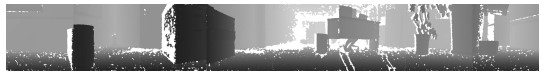
The depth map from Kinect. The intensity of each pixel means the distance.

The output of homing navigation.
6. Moment metric model
The environment has some constant distribution of landmarks and it has to be measured to build the navigation model. We made specific measurement of moment metric function. It has both range and characteristic variable like color or height. Then the distribution of this model has unique convergence point which can be used as center.


Designed moment metric function and homing navigation model

The simulation output of homing navigation based on moment metric model
7. Haar-like feature based model
Haar-like feature is well known feature used in face detection. We apply it into navigation model. As one simple Haar-like feature is not strong classifier, the combination of simple masks can be strong one. Therefore we gather robust masks among random generated ones and also calculate the matching score of them to make landmark vector. Then it can find the homing direction.


The example of simple masks(left) and reconstructed image using selected masks.