IMU with Kalman filter
Kalman Filter Algorithm
The Kalman filter was developed by Rudolf E. Kalman. Its purpose is to use measurements observed over time, containing noise and other inaccuracies, and produce values that tend to be closer to the true values of the measurements and their associated calculated values. The Kalman filter has many applications in technology, and is an essential part of space and military technology development. The Kalman filter produces estimates of the true values of measurements and their associated calculated values by predicting a value, estimating the uncertainty of the predicted value, and computing a weighted average of the predicted value and the measured value. The most weight is given to the value with the least uncertainty. The estimates produced by the method tend to be closer to the true values than the original measurements because the weighted average has a better estimated uncertainty than either of the values that went into the weighted average. For the linear system, linear Kalman filter is used and for the non-linear system, extended Kalman filter (EKF) can be applied. Following picture shows each algorithm.
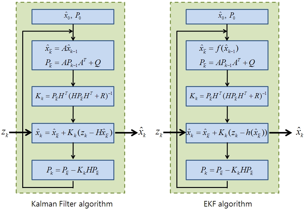
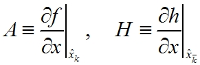
Z_k, the measurement is the input of the Kalman filter algorithm. And it uses A, H, Q, R from the system model. Then x_k becomes final output. Linear Kalman filter algorithm and extended kalman filter algorithm are almost same. But as the system model cannot be derived from the nonlinear system, linearization of system model is needed for EKF algorithm. f(x_k), h(x_k) are the nonlinear function from the nonlinear system. Jacobian can be used for the linearization like below:
Kalman Fusion
Accelerometer and gyroscope are hard to use separately to measure the position angle. Position angle that derived from the accelerometer has noise, while the gyroscope shows the drift. Though accelerometer gives noisy output, its measuring error is conservative. On the other side, gyroscope gives relatively noise immuned output for short time duration, though its error will be diverged for long time period. With these characteristics, we can see that two sensors are in complementary relationship. If gyro drift can be corrected by accelerometer, the output angle can have reliability. Likewise, by combination of two complementary sensors, improved output can be calculated. This is the concept of the Kalman fusion.
Euler angles and Inertial Measurement Unit (IMU)
The Euler angles are three angles introduced by Leonhard Euler to describe the orientation of a rigid body. To describe such an orientation in 3-dimensional Euclidean space three parameters are required. They can be given in several ways, Euler angles being one of them. Following picture shows the concept of the Euler angles well.
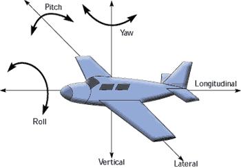
Rotational angle for the each x, y, and z-axis are called roll, pitch, and yaw. An inertial measurement unit, or IMU, is an electronic device that measures orientation and gravitational forces using a combination of accelerometers and gyroscopes. IMUs are typically used to maneuver aircraft, including UAVs, among many others, and spacecraft, including shuttles, and satellites. The IMU is the main component of inertial navigation systems used in aircraft, spacecraft, watercraft, and guided missiles among others. Simply, IMU measures the Euler angles.
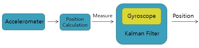
To get the reliable position angle(Euler angle) with accelerometer and gyroscope, Kalman fusion is needed. Following figure shows the concept of Kalman fusion in IMU.
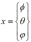
To perform the Kalman fusion, system model, A, H, R, and Q should be decided. Interested variables are pi, theta and ro. So, the state variable can be set as like follows:
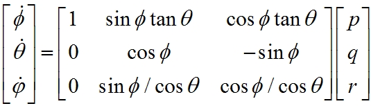
From this relationship, we can get system model:
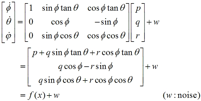
But the system model, f(x) is not linear. So, it has to be linearized by using Jacobian:
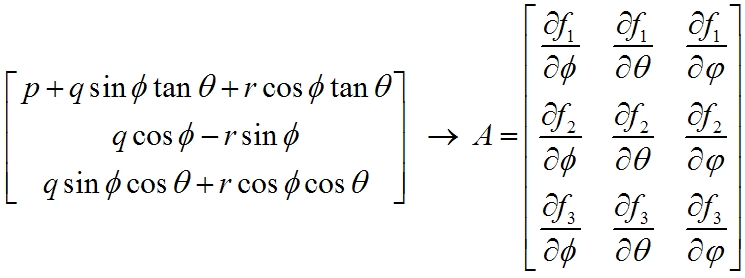
From above equation, system matrix A can be derived. And measuring model can be represented as:
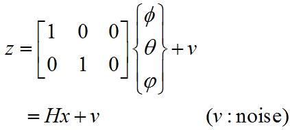
In this case, the system model is linear. So, simply system matrix H can be obtained. Finally, the system matrices A and H are derived. With this system model, Kalman filter algorithm can be applied. We implemented this algorithm to self-made IMU circuit. The pictures of the self-made IMU are attached below:
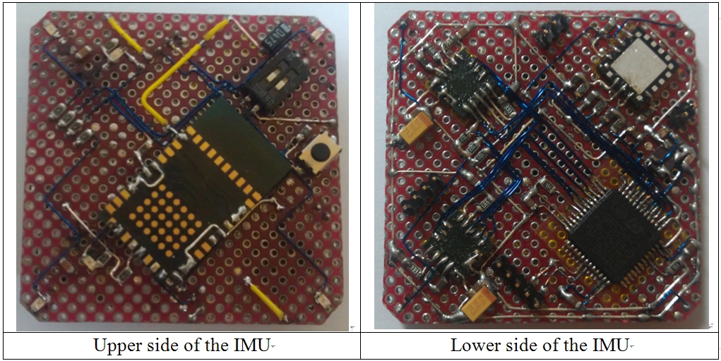
IMU is implemented on 32mm X 32mm size PCB. On the upper side, LMX9838 Bluetooth serial port module is attached, and on the lower side, MMA7260 (3-axis MEMS accelerometer) and two LPY530AL (dual axis MEMS gyroscope) are mounted as sensor. And to compute the Kalman fusion, STM32F103C8T6 (32-bit ARM Cortex-M3) processor is used. It uses 8MHz external crystal and by using inside PLL circuit, it can runs at 72MHz. It can calculate Kalman filter algorithm more than 1000 time per 1sec with powerful engine. Following shows the circuit block diagram.
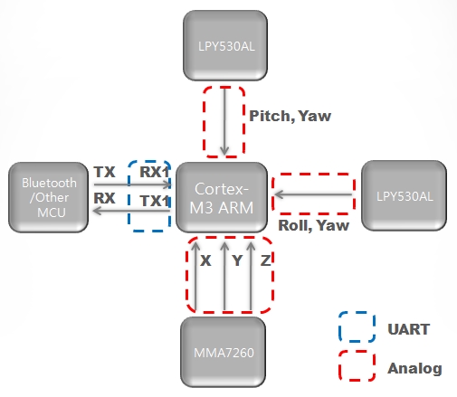
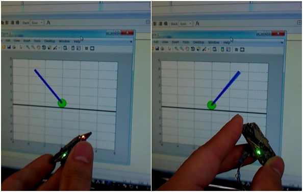
The output of the MMA7260 Accelerometer and the LPY530AL gyroscopes are the analog signal. These signals are converted into digital data by using STM32F103C8T6’s internal 12-bit analog-to-digital converter. Updated result can be transmitted UART communication protocol via Bluetooth or direct connection of other system. As MATLAB supports UART serial communication, IMU data can be collected with MATLAB. Attached picture below shows the result with real-time MATLAB plotting of the IMU data.
Quadrotor with IMU
Quadrotor
A quadrotor, also called a quadrotor helicopter or quadrocopter, is an aircraft that is lifted and propelled by four rotors. Following shows the schematic of reaction torques on each motor of a quadrotor aircraft, due to spinning rotors.
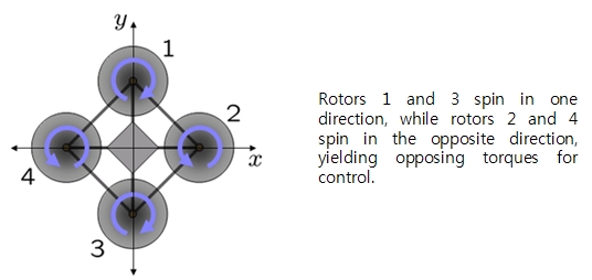
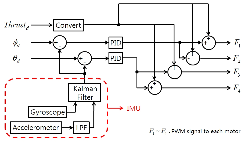
In quadrotor system, each rotor produces both a thrust and torque about its center of rotation, as well as a drag force opposite to the vehicle's direction of flight. If all rotors are spinning at the same angular velocity, with rotors one and three rotating clockwise and rotors two and four counterclockwise, the net aerodynamic torque, and hence the angular acceleration about the yaw axis is exactly zero, which implies that the yaw stabilizing rotor of conventional helicopters is not needed. Yaw is induced by mismatching the balance in aerodynamic torques. Angular accelerations about the pitch and roll axes can be caused separately without impacting the yaw axis. Each pair of blades rotating in the same direction controls one axis, either roll or pitch, and increasing thrust for one rotor while decreasing thrust for the other will maintain the torque balance needed for yaw stability and induce a net torque about the roll or pitch axes. This way, fixed rotor blades can be made to maneuver the quad rotor vehicle in all dimensions. Translational acceleration is achieved by maintaining a non-zero pitch or roll angle. Based on these flight control method, following control block diagram can be used.
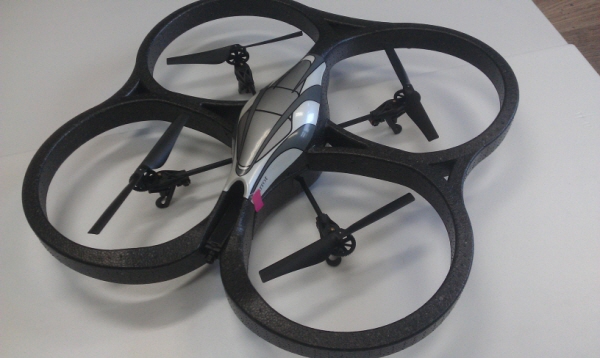
Quadrotor hardware that we built are shown below.
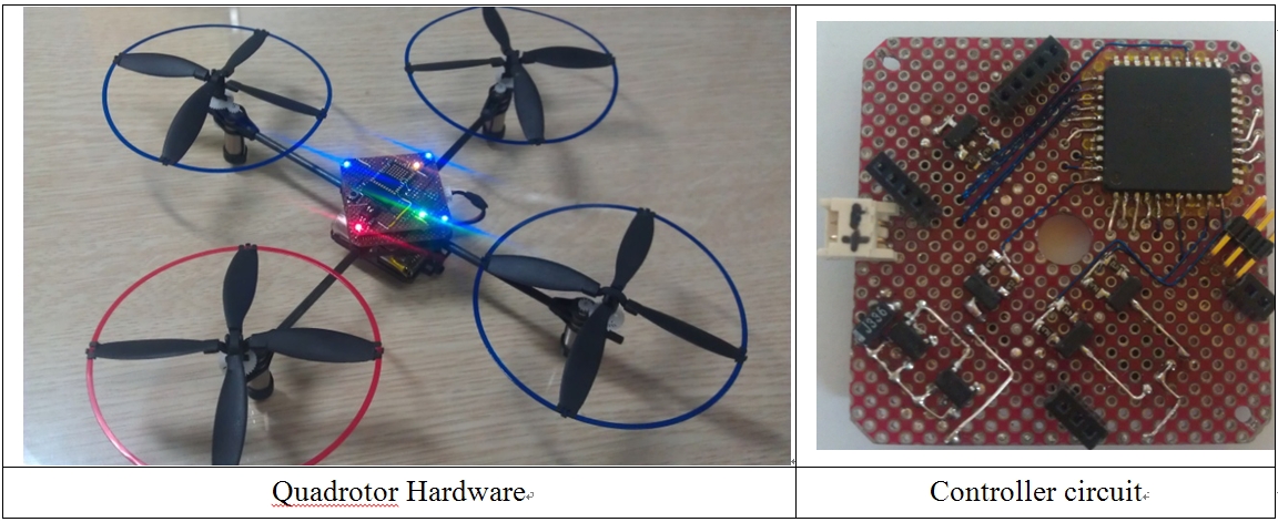
There are 4 rotors to control, so it takes 4 PWM channels, and to get the position angle data from the IMU, 1 UART communication channel is needed. And to communicate with PC, 1 more UART channel is required. So, we chose ATmega162 as controller, which has 6 PWM channels and supporting 2 UART communication channels. Each rotor can be driven by IRLML6502 HEXFET with PWM signal from the ATmega162. Controller circuit has same size with IMU module that we build and designed to mount IMU module.
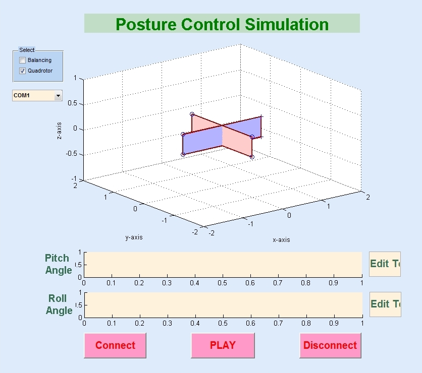
IMU tester with MATLAB GUI
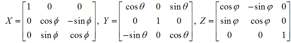
And to check the status of the robots, we made GUI program with MATLAB. By using UART serial communication, posture data(Euler angles) of robots can be transfer to MATLAB. For the roll, pitch, and yaw, three rotation matrices X, Y, and Z can be calculated:
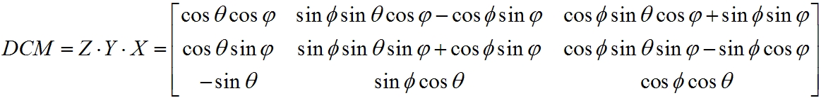
Then, direction cosine matrix (DCM) is given as:
With this matrix, representing of robot’s posture in 3-dimensional space is possible. Following figure shows the MATLAB GUI program for the quadrotor.